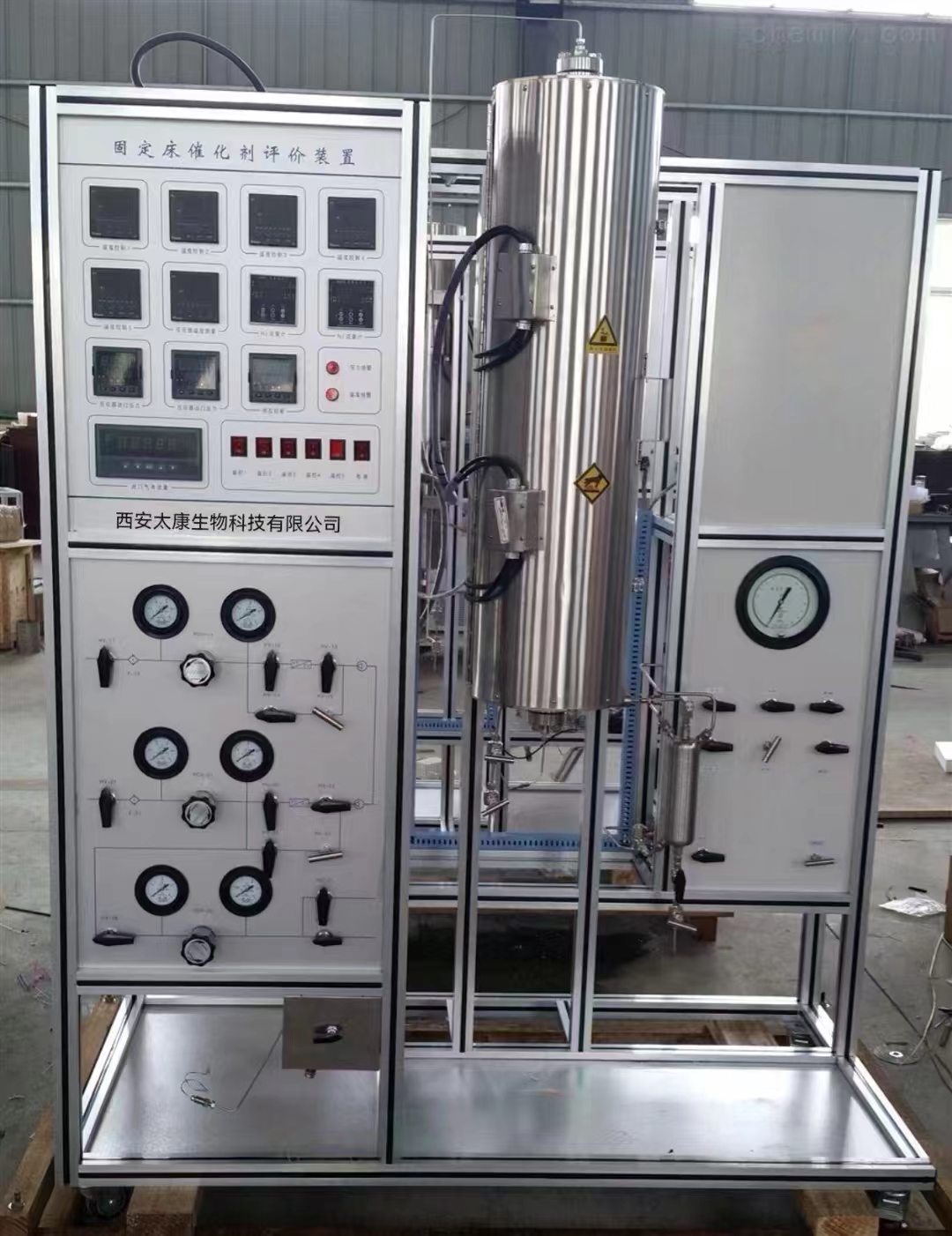
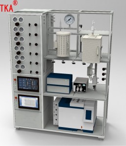
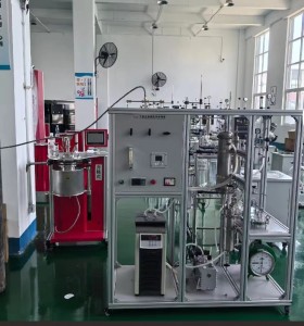
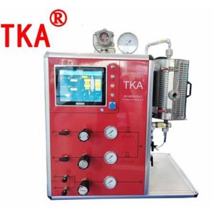
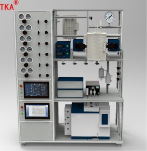
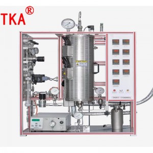
Fixed Bed Hydrogenation Reactor
Device process operation instructions and parts description
The device process oil six systems: gas feeding system, liquid feeding system, reaction system, condensation and separation system, liquid level control and recovery system, tail gas automatic discharge and measurement system.
1.Gas feeding system
The two gases are hydrogen (H2) and nitrogen (N2), the feeding method is as follows:
Hydrogen (H2) entering the system by two-way ball valve (HV-11), filtered by filter (F-11), the filtered gas is reduced to the target pressure by pressure reducing valve (PCV-11), controlled and metered by mass flow controller (FT/FV-11), and enters into the reaction system after passing through check valve (CK-11). The two-way ball valve (HV-14) and needle valve (HV-15) are mass flow controller (FT/FV-11) bypass valves. Pressure reducing valve (PCV-11) inlet pressure 0-6000psi, outlet pressure 0-1500psi adjustable, pressure reducing valve inlet and outlet with pressure gauge (PI-11), pressure gauge (PI-12) to measure the pressure. Mass flow controller (FT/FV-11): control range 0-500ml/min, control accuracy: ± 1 per cent
Nitrogen (N2) entering the system from the two-way ball valve (HV-21), filtered by the filter (F-21), filtered gas is reduced to the target pressure by the pressure reducing valve (PCV-21), controlled and metered by the mass flow controller (FT/FV-21) and enters into the reaction system after passing through the check valve (CK-21). The two-way ball valve (HV-24) and needle valve (HV-25) are bypass valves for the mass flow controller (FT/FV-21). Pressure reducing valve (PCV-21) inlet pressure 0-6000psi, outlet pressure 0-1500psi adjustable, pressure reducing valve inlet and outlet with pressure gauge (PI-21), pressure gauge (PI-22) to measure the pressure. Mass flow controller (FT/FV-21): control range 0-500ml/min, control accuracy: ±1 per cent
Nitrogen can also be delivered to the product tank (V-52) and raw material tank (V-31) for use through a two-way ball valve (HV-26), reduced pressure by a pressure reducing valve (PCV-22), and a two-way ball valve (HV-27) and a three-way ball valve (HV-31). Pressure reducing valve (PCV-22) inlet pressure 0-3500psi, outlet pressure 0-250psi adjustable, pressure reducing valve inlet and outlet pressure gauge (PI-23), pressure gauge (PI-24) to measure the pressure.
2.Liquid feeding system
After weighed by the electronic balance (WT-31), the liquid material is filtered by the raw material tank (V-31) through the three-way ball valve (HV-32) and liquid filter (F-31), and then injected into the reaction system through the precision pump (p-31) with a certain flow rate through the three-way ball valve (HV-33) and check valve (CK-31). The electronic balance (WT-31) has a range of 30Kg and a precision of 1g. The raw material tank (V-31) has a volume of 3L and a pressure resistance of 2.5Mpa.
Precision metering pump is equipped with pressure upper limit protection, and a safety valve (PSV-31) double pressure protection, in order to prevent the pump outlet pressure abnormal overpressure damage to the precision metering pump. Precision metering pump flow control range 0.001-12ml/min, pressure 6000psi.
3.Reaction system
After metering the gas phase and liquid phase principle into the reactor (R-101) for catalytic reaction. The reaction temperature is heated by the reactor (FRN-101) to ensure the reaction temperature.
A pressure transmitter (PI-101) is installed at the inlet of the reactor (R-101) to measure the inlet pressure of the reactor and a safety valve (PSV101) is installed to prevent the reactor pressure from exceeding the normal value. The unit is equipped with three types of reactors for different catalyst filling volumes. The inner diameters are 9mm, 12mm and 16mm with an effective length of 1000mm for 30ml, 50ml and 100ml catalyst filling respectively. Working temperature of the reactor: room temperature-500℃, working pressure: 10MPa, pressure transmitter range 16Mpa measuring accuracy 0.01Mpa.
The reactor (FRN-101) is an open-type heating furnace with five temperature control sections, namely (TIC101), (TIC102), (TIC103), (TIC104), (TIC105), and the temperature control range is room temperature-500℃. There is a temperature measuring probe (TI106) inside the reactor. The temperature controller is programme temperature rise with upper limit alarm function and solid state relay output. The thermocouple is type K.
The reactor outlet is designed with a sampling port, sampling through the valve (HV-101), valve (102), to ensure real-time sampling and analysis of the reaction process.
4.Condensation separation system
After the reactor reaction products, through the condenser (HE-41) cooling, into the gas-liquid separator (V-51) for gas-liquid separation. The separated product of gas-liquid separator (V-51) is divided into two parts: gas phase and liquid phase.
According to the needs of the reaction, the water inlet of the condenser (HE-41) can be adjusted to control the zui final temperature of the condensed product.
5.Liquid level control and recovery system
The liquid level in the gas-liquid separator (V-51) is measured by the liquid level meter (LT-51) and adjusted by the liquid level adjustment valve (LV-51). The liquid phase that flows through the filter (F-51) and level control valve (LV-51) enters the product tank (V-52) and is weighed by the electronic balance (WT-51). The two-way ball valve (HV-55) and needle valve (HV-56) are bypass valves for the level control valve (LV-51).
The electronic balance (WT-51) has a range of 30Kg and an accuracy of 1g.
6.Automatic exhaust gas discharge and metering system
The non-condensable gas separated by gas-liquid separator (V-51) is filtered by gas filter (F-61) and then adjusted by digital pressure regulating valve (PCV-61) to ensure the system pressure is stable, and the outflow is measured by wet gas flow meter (WTM-61) and then discharged for disposal. Sampling valve (HV-65) allows real-time sampling. The two-way ball valve (HV-63) and needle valve (HV-64) are bypass valves for the digital pressure control valve (PCV-61).
Digital Pressure Control Valve (PCV-61) regulates pressure control range: 0-2500psi.
The gas flow meter (WTM-61) has a flow measurement range of 0-0.2m3/h.


